

|
|
||||
|
|
|||||
| Preparing a Selene for International Shore Power (Part 2) | ||||
|
By Capt. Mark Tilden This article was republished by permission from Passage Maker Magazine. In part 1 of this article, we discussed four key factors to consider in preparing for plugging into international power:
In this second part, we'll look at three approaches to preparing your boat for international shore power and outline the advantages and disadvantages of each. "Power Tolerant" Equipment If you're careful and selective, it is possible to find equipment that will run on most international power. Be sure to check the specifications for frequency range as well as voltage. Many of the small plug-in transformers that we use to power our laptop computers, digital cameras, and cell phones, for example, will run on just about any power from about 100V to 250V and 50 or 60 Hz. Check the labels carefully. Most heating appliances—electric heaters, frying pans and toasters, don't really care what frequency they run on, though they typically require a fairly narrow range of operating voltage. Be careful, however, if the appliance has a heating element and a motor—like a hair dryer, since the heating element will probably work fine on 50 Hz or 60 Hz, but the motor may not. Some devices with electric motors will run on 50 Hz or 60 Hz, but they'll run slower on 50 Hz and might be a bit less efficient. For example, the air conditioning system on our Selene Trawler will operate on 50 Hz or 60 Hz, but it runs a bit slower on 50 Hz, since this type of motor depends on the line frequency to determine its speed. Don't forget your battery chargers and other permanently installed equipment. This equipment must also be selected to handle both frequencies if you want to take this approach to shore power preparation. The key in selecting equipment is to read the specifications carefully. If you elect this approach, you'll probably also need a transformer to convert shore power voltages into the correct range for your equipment (i.e. down from 240V to 120V or up from 120V to 240V). Some transformers have "taps" that allow you to configure the transformer to step-up or step-down the shore power voltage by changing the input and output connections with either some manual re-wiring or a switch. Another useful feature is an automatic "boost" function that will provide some automatic compensation for line voltage fluctuations. There are important safety reasons for installing an isolation transformer anyway, so if you're cruising to areas with different line voltages, consider a transformer with taps and a boost function so that it can handle a variety of input voltages and help isolate your boat from some of the fluctuations of the incoming shore power. Remember that if you're cruising in areas with different shore power frequency than your home, the transformer must be specified to work with 50 Hz or 60 Hz. Running a transformer designed for 60 Hz only on a lower frequency will cause it to draw more current and run hotter, so be sure that the transformer is designed to work with 50 Hz or 60 Hz. Also, the transformer will not convert the frequency. Whatever line frequency is on its input will be reflected by the output of the transformer. The advantage of this approach to shore power management is that it may be the lowest cost (though equipment that will run on a different frequencies and line voltages may be more expensive than other, more common models). The disadvantage to this approach is that you must be extremely careful to keep track of what equipment can be safely operated on the shore power you're currently connected to. It's easy to forget and plug something in that won't handle 50 Hz power or different voltages. All of your permanently installed equipment must either handle the various shore power inputs or be disconnected. Covers over critical circuit breakers should be installed to avoid accidentally turning on devices with incompatible power. Also, keep in mind that many electronic devices, such as TV's and computers must not be connected to incompatible power, even if they're left off. That's because many electronic devices are actually in a "standby" mode when they're switched off. These devices must be completely disconnected or at least shut off at a circuit breaker. Making Your Own Juice Another approach is to simply not depend on the shore power supplies at all and run an on-board generator whenever the local shore power is incompatible with your equipment. Of course, running your generator 7x24 is expensive and won't do much for your reputation on the dock either. Also, prolonged operation of your generator at load levels below about 70% of its rated capacity can cause a variety of long-term problems with the generator's engine, so it's not advisable. Making your own AC power with an inverter may be more practical—at least for reasonably small loads, up to about 4 kilowatts (with equates roughly to 30 amps at 120V). Larger inverters are also available and some models allow you to gang several inverters together to increase capacity. Remember, however, that every amp of 120V AC power you use from an inverter requires 12 – 15 times that many amps of 12 volts or 6 – 7 times that many amps at 24 volts to run the inverter. A 1500 watt appliance operating on an inverter will use around 140 amps at 12 volts and 70 amps at 24 volts. At those rates, it doesn't take long to discharge even a substantial house battery bank. In addition, motor driven appliances, such as refrigeration and air conditioning often require several times their normal operating current for a brief period at startup. Fortunately, most inverters can also provide brief surges of additional power above their continuous rating. Be sure to account for these startup loads when you calculate the amount of inverter capacity you need. If several motors start simultaneously (as may happen when you turn on a multi-zone air conditioning system, for example), the system may draw a huge startup current as several compressor and fan motors try to start simultaneously. You'll also need a big house battery bank and/or large battery chargers to replenish all those amps you use. If you use your generator to charge batteries, you'll need to be sure that your house battery bank is large enough to handle the inverter loads over the period of an evening when you can't (or don't want to) run the generator. When you do start the generator, you want to be able to re-charge the batteries in a reasonable period of time. The rule of thumb is that your charging sources need to be able to supply at least 20% of the amp-hour capacity of your battery bank. For a 1200 amp-hour battery bank, you'll want at least 240 amps of charging capacity. Early inverters, and many of the low-cost smaller inverters today generate a "modified sine wave" output, instead of a pure sine wave. While many AC-powered devices will work fine on these inverters, there are several disadvantages to modified sine wave inverters, including substantially increased radio frequency noise that can be very detrimental to the performance of radios and TV reception as well as other sensitive electronics. The extra cost of a pure sine wave inverter is well worth the investment for most cruising boats. If your battery chargers will run on 50 Hz or 60 Hz, you may be able to run the battery chargers on shore power and use one or more inverters to create the appropriate power for your on-board AC power needs. You can run your battery chargers on 50 Hz 240-volt shore power and produce 120V 60 Hz AC from your inverters for your appliances. Short term peak loads can draw power from the batteries and as long as your inverter capacity is large enough, the output voltage should be quite stable and independent of shore power line voltage fluctuations. If you plan to run your system in this mode over extended periods, the battery chargers must be capable of supplying enough current to stay ahead of the average demand from the inverters and re-charge the batteries after periods of peak demand. Figure 1 shows a simplified diagram of a typical battery charger/inverter setup.
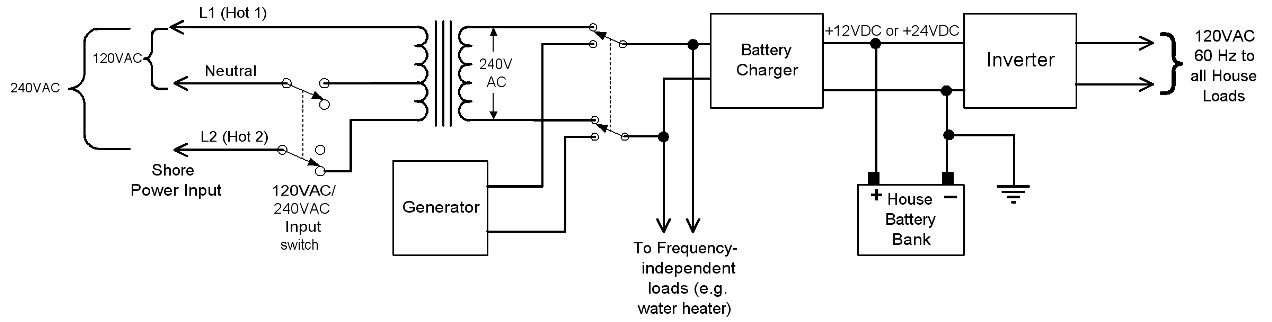 Figure 1. A simplified diagram of a bettery charger/inverter setup for creating 60Hz power regardless of input frequency. (Click on the image to enlarge.)
This system requires an isolation transformer that can handle 50Hz or 60Hz input, as well as a battery charger with the same capability. Using a 240V battery charger works best because 220-240V shore power is more common around the world than the lower 120V. If the isolation transformer has a center tap on the input winding, as shown in this diagram, you can also add a switch that takes advantage of the center tap to step up 120V input to 240V. You might also want to consider an isolation transformer with boost capability, so that your system will be able to handle lower voltages (such as the less common 208V power) and help compensate for line voltage fluctuations. Keep in mind, however, than when you plug in to 120V outlets using the transformer center tap, it takes twice as many amps to create the same total power as when you're plugged into 240V. As a result, you'll probably want to make sure you have the ability to control the amount of current your battery charger uses to avoid tripping the circuit breaker on the dock. Many modern battery chargers have functions that allow you to throttle the battery chargers to limit the amount of power they use. Of course, this also limits the amount of AC power you can use from the inverters over the long-term because the battery charger must be able to replace all that power in the battery bank. Many boats have combined battery charger and inverter units installed because they're less expensive and use less space than separate units. This works great where the available shore power is compatible with your on-board electrical requirements. Usually, when there is shore power present, these combined units simply pass through the shore power. Some may be capable of supplementing the shore power adding inverter power to the shore power to handle temporary load peaks. However, most of these combined chargers/inverters cannot be run as a charger and inverter simultaneously, with different frequencies on the input and output. For example, you generally can't plug your boat into 50 Hz shore power and expect your combination charger/inverter to put out 60 Hz AC. If you want to generate your own AC using inverters, and charge your batteries using battery chargers that will run on 50 Hz or 60 Hz, you'll need to install separate charger and inverter units, and you'll need to insure that the boat internal AC loads are connected only to the inverter outputs, and not to shore power. Some appliances, such as air conditioning systems, may be capable of operating on 50 Hz power, so you can run these systems directly on the shore power, while running other frequency and voltage sensitive devices on the inverters. This approach has several advantages:
This system can be used seamlessly without AC power interruption whether you're plugged into shore power or not. Of course, you'll have to charge the batteries sooner or later with either battery chargers that can handle the local shore power, or by running your generator. The disadvantages include:
Shore Power Converters Several companies produce specialty shore power converter devices that are specifically designed to accept a wide variety of shore power frequency and voltage and convert it to a constant voltage and frequency for use on board. The converters accept the AC input from shore power and convert it to DC power internally. Then a built-in high-efficiency inverter takes the DC power and creates your desired AC output voltage and frequency. Initially, these units were only practical on very large yachts with large power requirements and equally large budgets. However, in recent years shore power converters have come down in size and cost and microprocessor technology even makes them increasingly intelligent. Some are even able to automatically start generators when input shore power fails or falls below certain thresholds, and automatically re-start themselves when shore power is restored after a failure. They're still not cheap, but converters offer the most flexible, universal power conversion option. Typically, shore power converters will accept a wide variety of input voltages from about 170 to nearly 500 volts and input frequencies from about 40 Hz to 70 Hz. The output frequency and voltage are usually fixed and configured at the factory. The converters handle all three of the main shore power variables: frequency conversion, converting the nominal line voltage to a stable desired voltage, and isolating on-board systems from voltage fluctuations and transients in the shore power. In addition, most also have built-in isolation, so they provide the same safety and galvanic corrosion protection as an isolation transformer. The advantages of a solution are:
Disadvantages of this approach include:
Our System When we built our 60' Selene trawler, we studied several options for preparing for international power. Our goal was to create a flexible shore power system that would handle world-wide shore power, while offering as much redundancy as we possible within our budget and space constraints. As is often the case on vessels with air conditioning or other large loads, our Selene was equipped from the factory with two 50 amp shore power circuits. Typically, one circuit is intended to power the air conditioning systems on board, and the other powers the remainder of the loads. Because our air conditioning systems can operate on 50Hz or 60Hz power, we decided to install a simple 50Hz/60 Hz isolation transformer on one of the shore power circuits. We installed an ASEA Power Systems 12KVA power converter on the second shore power circuit. To provide redundancy, we added cross-over switches that allow both the isolation transformer and the frequency converter to be connected to either of the shore power circuits. Figure 2 shows a simplified diagram of our system.
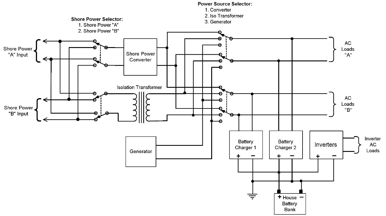 Figure 2. A simplified diagram of the system we installed on our Selene 59 (Click on the image to enlarge.)
If we are at a dock with abundant 50 Hz or 60 Hz shore power, we can run the air conditioning through the isolation transformer on one of the 50-amp circuits, and the rest of the house loads on the second circuit. In addition, the AC circuit breaker panel is split into two halves, "A" and "B". Each half of the panel can be powered by the output of the shore power converter, the isolation transformer, or the generator. In the event that the shore power converter were to fail, all the loads can be switched to the isolation transformer (obviously, within the limitations of the single 50-amp circuit), or the generator. We installed two independent battery chargers—one tied to each of the "A" and "B" shore power circuits, as well as two 4KW inverters for powering 120V loads while we're at anchor without the generator running. All the 120V loads can be run either on the inverters or directly on the AC output from the frequency converter or isolation transformer (switching for the 120VAC loads is not shown on the diagram for simplicity). Since the battery chargers can operate on either 50Hz or 60Hz input power, they provide a backup for the shore power converter by running them through the isolation transformer and making 120V power from the inverters. We've installed an isolation transformer with a center tap and switching, similar to the setup shown in Figure 1 for locations that only have 120V power. That switching is omitted in figure 2 for clarity. Both diagrams also omit numerous circuit breakers in the system for over-current protection. Making Your Own Choice Preparing for international shore power is one of those places where Ben Franklin's famous quote really applies: "An ounce of prevention is worth a pound of cure." While sorting through the options and details now may not be a lot of fun, taking the time do work through these issues now will certainly make life easier and more fun when you pull into that beautiful marina in paradise and want to plug in to chill the drinks. Since there are many critical safety requirements for shore power systems, the detailed design and installation of the system are best left to qualified engineers and technicians. However, armed with the concepts and options discussed here, you should be able to have a productive conversation with your builder, engineer, or shipyard and make an informed decision about the best option for your boat, your equipment, and your cruising plans.
|
||||
 
| ||||
| Copyright (c) MDT Consulting, LLC 2007. All rights reserved. | Visit the Selene manufacturer's web site | Use & Privacy Policy | Contact us | |